
6. Hardware
Hardware details for paperd.ink
Block Diagram
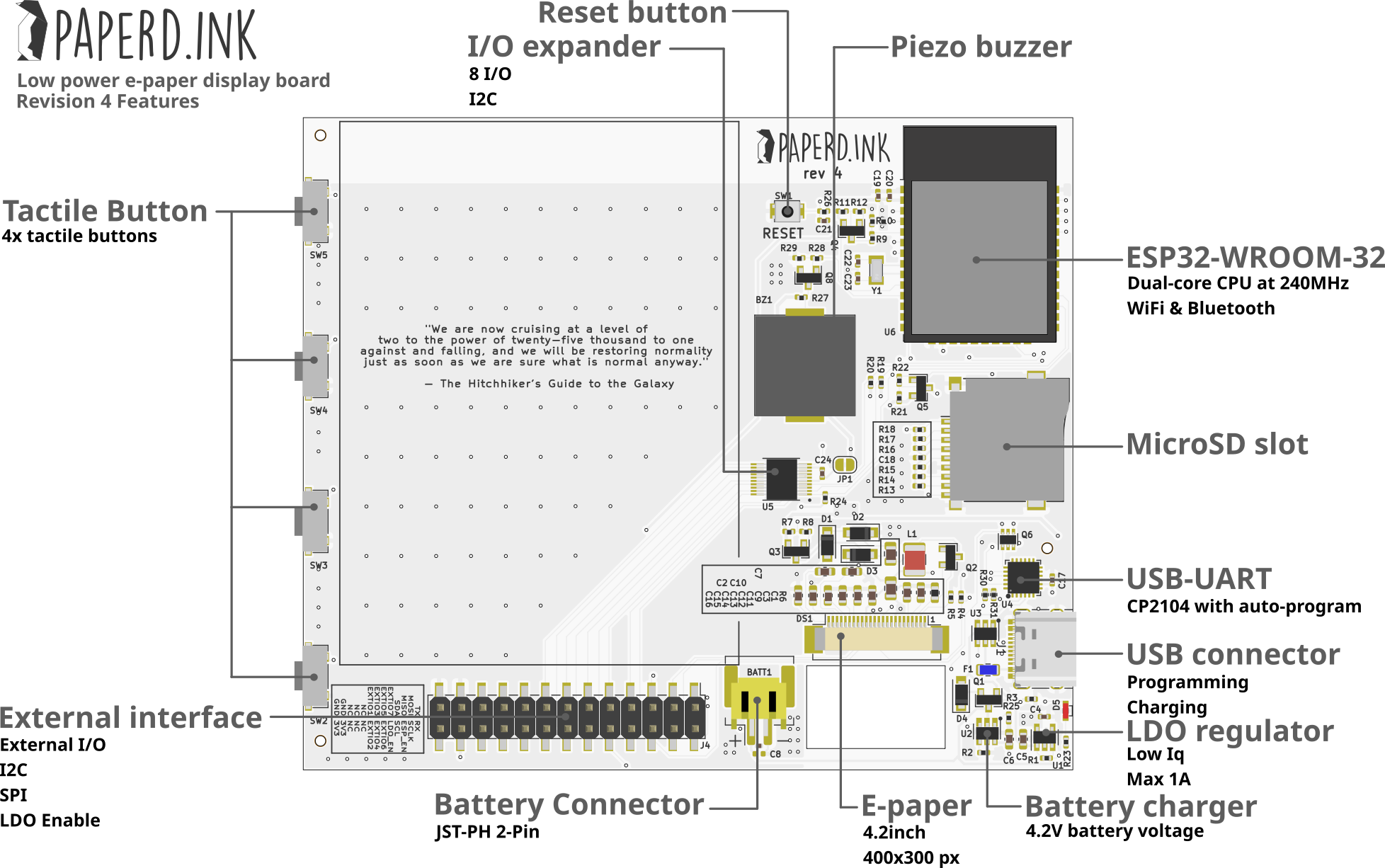
Specifications
- ESP32-WROOM-32 powerful module
- FCC/CE Certified WiFi & Bluetooth wireless connectivity to unlock the full potential of paperd.ink
- Tri-color & monochrome 400x300 px e-paper displays for the 2 variants Merlot and Classic
- <20uA current consumption in sleep mode means longer battery life and more freedom to create
- CP2104 USB-UART converter onboard for easy programming and updates
- MicroSD Card slot for convenient storage of images, files, and more
- Piezo Buzzer provides notifications and alerts for a more interactive experience
- 4x Tactile Buttons for user input and control
- Extension Header for easy interfacing and expansion of capabilities, enabling limitless creativity and hacking possibilities
- 1900mAh LiPo battery allows you to keep your e-paper projects running without worrying about running out of power
- Battery Charger circuit to keep it truly wireless
Pin Map
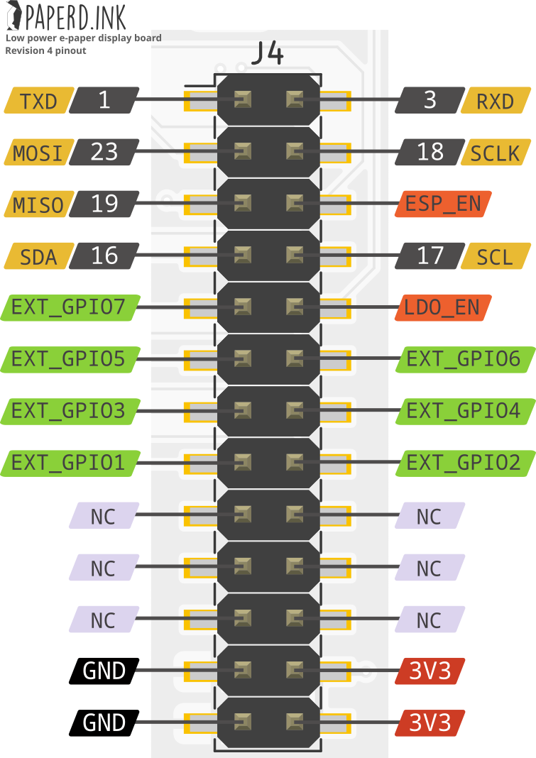
- UART, SPI, and I2C so you can easily add external sensors and modules to your paperd.ink device, making it highly extendable and customizable. This means you can create even more complex and sophisticated e-paper display projects.
- 8 I/O pins for controlling any output and receiving any input.
- Save power with paperd.ink. The ESP_EN pin allows you to disable the ESP32 module when you need to, and the LDO_EN pin lets you disable the entire board for virtually no current consumption.
- High battery life using the LDO_EN pin which lets you disable the entire board, reducing power consumption to virtually zero and allowing you to conserve battery life for your e-paper projects.
- Pin definitions header file is here →.
I2C Pins
- SDA: GPIO16
- SCL: GPIO17
SPI Pins
- SCK: GPIO18
- MOSI: GPIO23
- MISO: GPIO19
SD Card Pins
- SD CS: GPIO21
- SD enable: GPIO5
E-paper Display Pins
- EPD CS: GPIO22
- EPD DC: GPIO15
- EPD BUSY: GPIO34
- EPD RESET: GPIO13
- EPD Enable: GPIO12
PCF8574 Pins
- PCF INT: GPIO35
- SD Chip Detect (low = SD card present): P4
- EXT GPIO1: P5
- EXT GPIO2: P6
- EXT GPIO3: P7
- PCF I2C ADDR (Rev 3): 0x20
- PCF I2C ADDR (Rev 4): 0x38
LiPo
- Charging indicator (low = charging): GPIO36
- Battery Enable: GPIO25
- Battery Voltage: GPIO39
- Battery Voltage ADC: ADC1_CHANNEL_3
Buzzer
- Piezo: GPIO26
Buttons
From top to bottom:
- Button 1: GPIO14
- Button 2: GPIO27
- Button 3: GPIO4
- Button 4: GPIO2
Components Interfacing
Paperd.ink is designed to be power efficient. Thus, the electronic paper display (EPD), SD card, and battery sense circuits are powered by a MOSFET that can be turned off when not in use. All enable pins are active low, meaning they must be set to low to turn on the circuitry.
For example, to use the EPD, set EPD enable pin (GPIO 12) to low to provide power to the EPD and perform necessary display functions. Once display is updated set the EPD enable pin (GPIO 12) to high to reduce power consumption.
Battery Specifications & Charging
paperd.ink Classic and paperd.ink Merlot come equipped with a 3.7V (nominal) 1900 mAh LiPo battery, which offers extended battery life for your e-paper projects.
paperd.ink devices have an inbuilt LiPo charger so the battery can be charged using a 4.2V charging voltage. Simply connect a type-C cable to charge the battery, and the red LED will light up to indicate that charging is in progress. Once charging is complete, the LED will switch off.
Design Files
Dimensions
- The PCB is 92.1 x 78.1 mm
- The enclosure is 98 x 82 x 16 mm